33+ signal conditioning block diagram
Modified AC Wheatstone Bridge Network for Accurate Measurement of Pressure Using Strain Gauge. The resistance transducers are commonly used for the dc.

All You Need To Know About A Signal Generator And How To Select One Function Generator Block Diagram Digital Signal Processing
Webb MAE 4421 3 Block Diagrams In the introductory section we saw examples of block diagrams to represent systems eg.

. The next DSP block is the digital phase estimation required to recover the signals carrier phase. January 20 2011 Rust. 44 161 777-6622 Toll Free.
As with other diagrams the initial version may abstract away most details and focus on the major physical blocks of functionality. Block diagrams consist of Blocksthese represent. One Omega Drive River Bend Technology Drive ISO 9002 Certified Northbank Irlam Manchester M44 5EX England Tel.
Download scientific diagram Block diagram of signal conditioner. The schematic diagram below show signal conditioning circuit for remote current loop temperature transmitter. The signal conditioning of data acquisition equipment is in many.
Typically though the hardware block diagram occurs first. The block diagram of dc. This thermocouple temperature transmitter is loop.
For BPSK QPSK and. A widely used carrier phase recovery scheme for PSK signals eg. Signal Conditioning System The measurand which is basically a physical quantity is detected by the first stage of the instrumentation or measurement.
Block diagram of a signal conditioning system The transducer is connected to one arm of. Provides support for NI data acquisition and signal conditioning devices. The resistance transducers like strain.
The writers of Signal Conditioning System Block Diagram have made all reasonable attempts to offer latest and precise information and facts for the readers of this publication. 44 161 777-6611 FAX. Signal conditioning system is shown in the Fig.
Provides support for Ethernet GPIB serial USB and other types of instruments. After the demodulation and filtering of both channels are completed a voltage dividing circuit equipped with duty cycle multiplier is used to.

Audio Signal Processing Using Time Frequency Approaches Coding Classification Fingerprinting And Watermarking Signal Processing Coding Quadratics

Top Down Mass Spectrometry Of 60 Kda Proteins From Methanosarcina Acetivorans Using Quadrupole Ftms With Automated Octopole Collisionally Activated Dissociation S Molecular Cellular Proteomics
2
Calameo 1983 Alfa Romeo 33 Workshop Manual

Understanding The Fundamentals Of Digital Communications National Instruments Coding Signal Processing Block Diagram

Mii And Rmii Routing Guidelines For Ethernet Advanced Pcb Design Blog Cadence Signal Processing Network Switch Guidelines
2
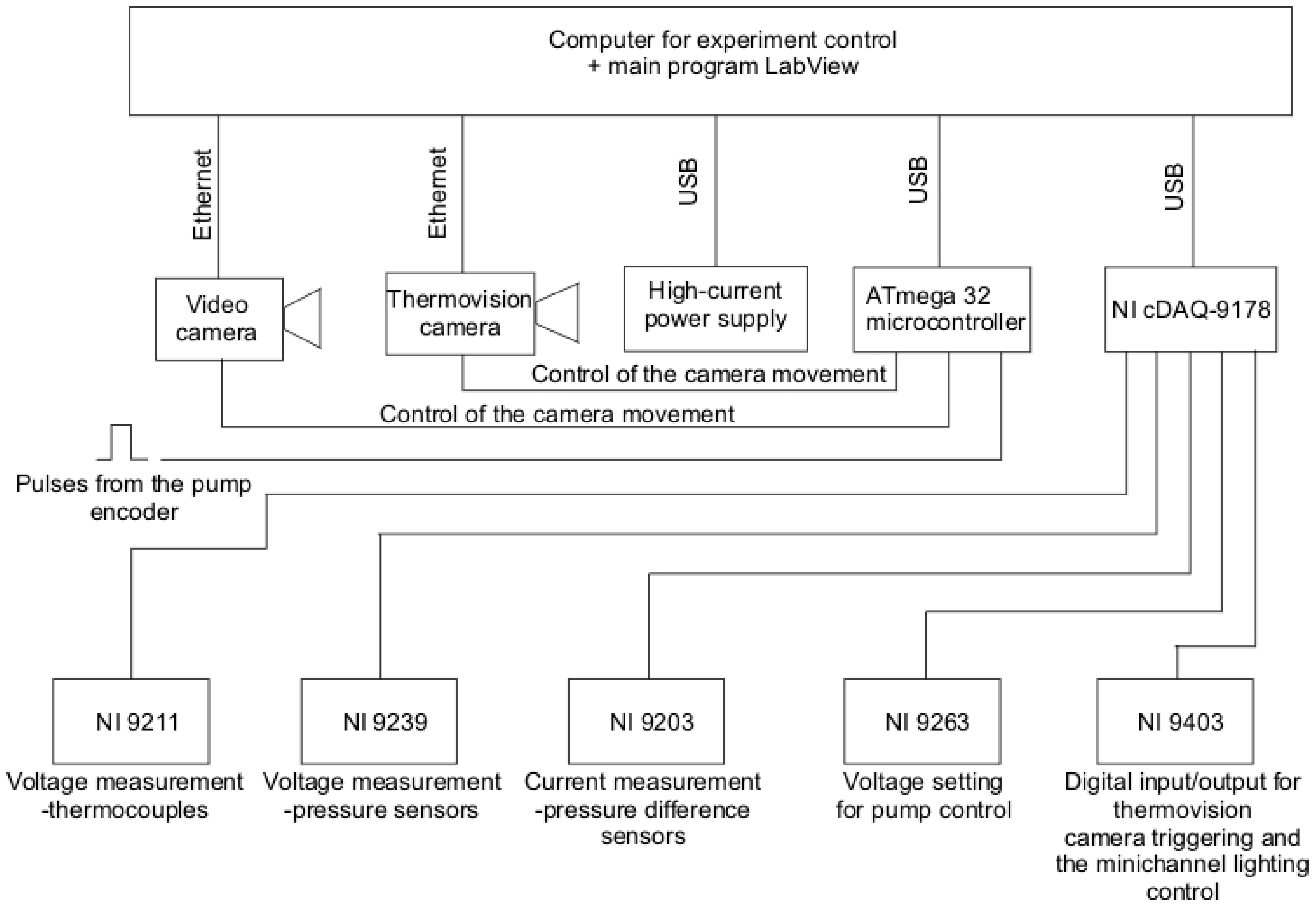
Energies Free Full Text Heat Transfer Coefficient Identification In Mini Channel Flow Boiling With The Hybrid Picard Trefftz Method Html

Rockwell Collins Dsp Receiver Example Block Diagram Receiver Digital

Hitachi Zx135us 6 Hydraulic Excavator Hydraulic Circuit Diagram By Heydownloads Issuu

An Introduction To Digital Signal Processing Digital Signal Processing Signal Processing Digital
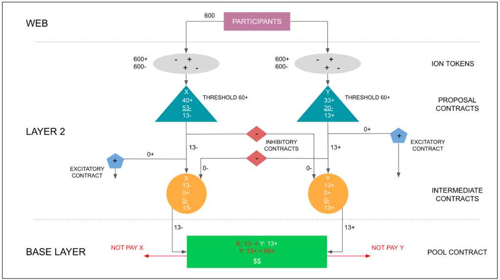
The Etherplan Consensus Engine Etherplan
2
2
2
2

Post Feature Image Block Diagram Mobile Phone Design Signal Processing